Modern turbocharged engines no longer rely on simple pneumatic wastegates alone. Electronic turbo pressure regulators — sometimes integrated into the turbocharger housing or mounted as standalone solenoid valves — modulate boost by controlling vacuum or pressure supplied to the wastegate or variable geometry actuator. The engine control unit compares requested boost against manifold pressure sensor readings and adjusts regulator duty cycle continuously. When that loop breaks down, drivers feel surging, flat spots, or unexpected power cutbacks long before a check engine light appears.
The Boost Control Loop and Its Components
A functional boost control system involves four primary elements: the ECU target map, the pressure regulator solenoid, the actuator that moves the wastegate or vanes, and one or more pressure sensors confirming actual manifold pressure. The ECU pulses the regulator at varying duty cycles to bleed or apply pressure to the actuator diaphragm. Higher duty cycle typically opens the wastegate further, reducing boost; lower duty cycle allows more boost to build.
- Manifold absolute pressure or boost pressure sensor provides feedback to the ECU.
- Charge air temperature and engine load inputs modify the target boost map dynamically.
- Some systems use a boost control solenoid plus a separate pressure transducer on the actuator line.
- Integrated electronic actuators eliminate vacuum lines but introduce their own motor and position sensor failure modes.
Understanding which architecture your engine uses prevents misdiagnosis. Replacing a wastegate actuator when the solenoid valve sticks open addresses the symptom briefly but leaves the root cause unresolved.
Surging Boost and Oscillating Manifold Pressure
Surging feels like the engine gains and loses power rhythmically during steady throttle application, often in the mid rpm range where the turbo transitions from spool to controlled boost. Causes include a sticking regulator valve that cannot maintain stable duty cycle, a leaking vacuum line that introduces unmetered air into the actuator circuit, or a failing pressure sensor sending erratic feedback that causes the ECU to hunt between overboost and underboost corrections.
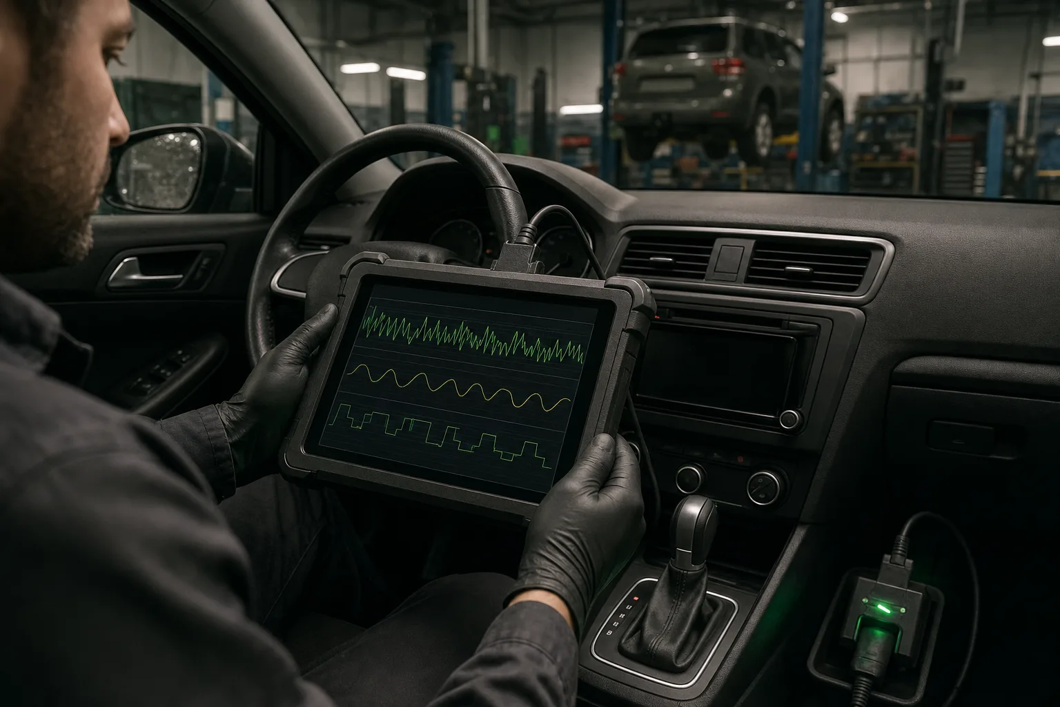
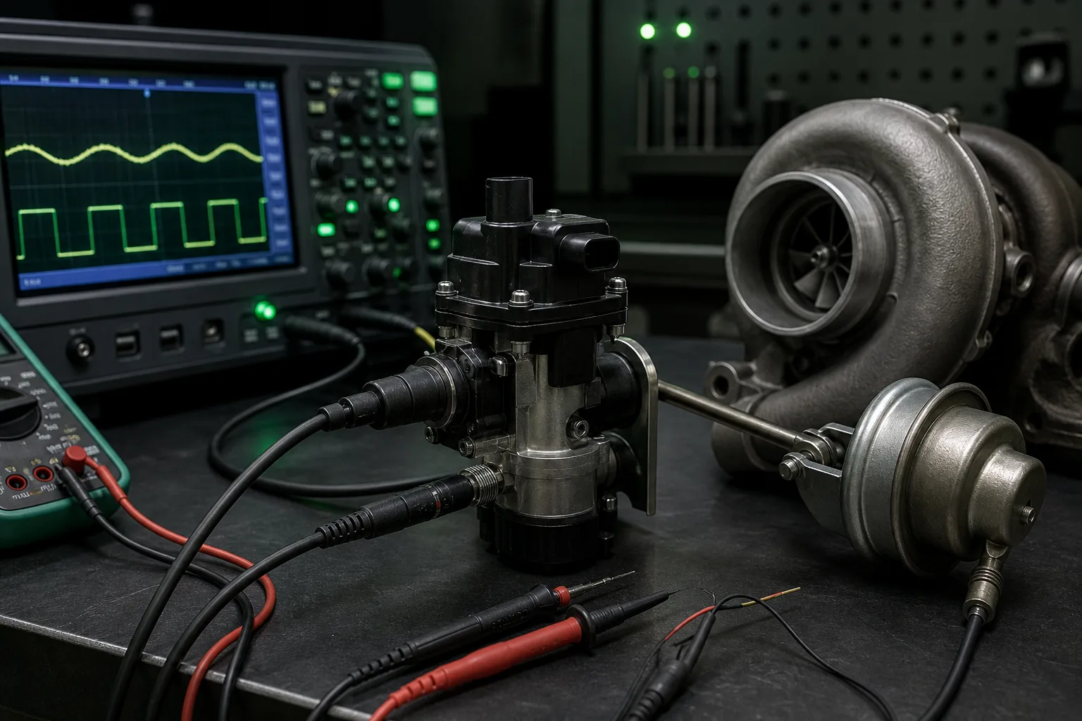
Oscilloscope capture of regulator duty cycle alongside manifold pressure reveals hunting patterns that scan tool live data may smooth over due to sampling rates. A healthy system shows pressure rising smoothly to target and holding flat under steady load. Surging systems display pressure waves of five to fifteen kilopascal amplitude at frequencies that match regulator pulsing. Technicians correlate these traces before replacing components to avoid swapping parts that test fine in isolation on a bench.
Mid-Range Flat Spots and Overboost Protection
Flat spots occur when requested boost never arrives despite rising rpm and adequate exhaust energy. The ECU may deliberately limit boost because sensor plausibility checks failed, or because the regulator cannot vent actuator pressure quickly enough during transient conditions. A partially blocked regulator vent port, carbon buildup on variable geometry vanes, or a cracked boost hose between the intercooler and throttle body all produce similar driver sensations with different root causes.
- Flat spot under hard acceleration with no fault codes often indicates mechanical sticking rather than electrical open circuits.
- Sudden power cut followed by limp mode usually triggers from overboost detection, not underboost.
- Smoke from the exhaust during surge events may point to turbo seal failure rather than regulator fault — correlation with oil consumption matters.
- Aftermarket tune changes can mask regulator problems until factory boost maps are restored for diagnosis.
Document whether the flat spot occurs at specific gears, specific rpm, or only when ambient temperature is high. Heat-soaked regulators and actuators behave differently from cold-start failures and guide whether heat shielding or component replacement is the appropriate repair path.
Voltage Drift, Wiring Faults, and Vacuum Leaks
Electronic regulators depend on stable supply voltage and clean ground paths. Corroded connectors in the engine bay, chafed wiring near hot turbo components, or poor ground straps create duty cycle commands that never reach the solenoid consistently. Voltage drop testing under load — not just static key-on measurements — identifies these faults before condemning the regulator itself.
Vacuum-operated systems remain vulnerable to leaks in small diameter hoses and one-way check valves. A leak upstream of the regulator allows unmetered air into the actuator circuit, causing sluggish wastegate response or failure to close fully at low boost targets. Smoke testing the actuator circuit with the engine off isolates leak locations faster than visual inspection alone in crowded engine bays.
A Structured Diagnostic Pathway
Effective turbo regulator diagnosis follows a sequence that confirms sensor accuracy, actuator response, and regulator command integrity before parts replacement. Clearing codes without road testing under the conditions that triggered the fault rarely provides lasting results.
- Verify boost pressure sensor readings against a mechanical gauge or trusted scan tool PID at idle and under load.
- Command the regulator through bi-directional controls and confirm actuator movement or audible solenoid clicking.
- Inspect vacuum lines, electrical connectors, and charge air plumbing for leaks, cracks, and heat damage.
- Capture oscilloscope traces of commanded versus actual boost during a controlled ramp from idle to peak torque rpm.
- Replace the regulator only after ruling out wiring, leaks, actuator binding, and ECU map anomalies.
After repair, perform a post-service road test that includes steady-state cruise, hard acceleration, and deceleration with throttle lift. Boost should build predictably without oscillation, recover quickly after gear changes, and remain within manufacturer limits under sustained load. Retain diagnostic traces in the service record so recurring complaints can be compared against the verified healthy baseline from the initial repair verification drive.